
F/A-18C/Litening II
The F/A-18 can carry the AN/AAQ-28 Litening II targeting pod. The Litening pod consists of three main elements. FLIR A/G functions are available in NAV and A/G master mode and A/A functions are available in A/A. The LTD/R and LST only have A/G applications and can be used in NAV or A/G master mode.
- Forward-Looking Infrared (FLIR) - A camera which has an infrared sensor and a charge coupled device (CCD), i.e. digital video. The FLIR can be used to locate, surveil, and designate targets on the ground and in the air.
- Laser Target Designator/Ranger (LTD/R) - A laser which performs both ranging functions to ground targets and designation for laser-guided munitions.
- Laser Spot Tracker (LST) - The LST provides the ability to locate laser energy which allows the pilot to locate where other aircraft are pointing their lasers. The lased point located by the LST may then be designated for weapon delivery or the FLIR and LTD/R can take over to track the same location.
The Litening can be mounted on station 4, 5, and 6. Its Stores Management Set identification is "FLIR". The targeting pod is interfaced with via the FLIR format, available on the [TAC] menu whenever the FLIR is powered. From the right console, the targeting pod components are controlled by three switches:
- FLIR
- ON: FLIR is powered and operating.
- STBY: FLIR is powered but in standby. It cannot be used and video is not supplied to the FLIR format. On initial power up (when placed in STBY or ON), the FLIR format will read "NOT TIMED OUT" while the FLIR is initializing.
- OFF: FLIR is off.
- LTD/R
- ARM: LTD/R is powered when the FLIR is and armed (laser can be fired). The LTD/R cannot be set to ARM outside of the A/G master mode. When set to ARM, the LTD/R can be used and the appropriate options are displayed on the FLIR format.
- SAFE: LTD/R is powered when the FLIR is and cannot be fired. No options are presented on the FLIR format. The SAFE position can be set by the computer itself in certain situations.
- LST/NFLIR
- ON: LST is powered when the FLIR is. This switch is so-named because of the additional functionality with the Navigation FLIR when instead using the ATFLIR targeting pod.
- OFF: LST is off.
Universally the FLIR format consists of the following indications and functions.

- FLIR Status - Indicates Operate (OPR) or Standby (STBY) and below ATRK or PTRK mode, if applicable.
- Zoom/Level/Gain - This pushbutton and the associated arrows adjust the level, zoom, and gain. Their associated values are displayed to the right. (Only zoom is available when Automatic Level and Gain is selected or when in CCD.)
- Not yet implemented.
- FLIR/CCD Toggle - Toggles between Forward Looking Infrared and Charge-Coupled Device camera modes. FLIR/CCD can also be toggled by pressing the FLIR FOV switch for more than 0.8 seconds when the Maverick or HARM is not selected in the SMS.
- White/Black-Hot Contrast - In FLIR camera mode, toggles between white-hot and black-hot modes. This changes whether temperature contrasting "hot" objects are indicated by a lighter vs. darker color.
- Automatic Level and Gain (ALG) - When boxed, the ALG function automatically adjusts level and gain.
- Grayscale - Displays a grayscale color strip for calibrating the level and gain. Also displayed is a maintenance error code sequence.
- Reticle - Toggles display of the FLIR reticle.
- Freeze - Freezes the current FLIR image.
- FOV Toggle - Toggles between wide and narrow FLIR field of view (FOV). This can also be toggled by pressing the FLIR FOV switch for less than 0.8 seconds.
- Horizontal Position - Current FLIR position left or right of aircraft boresight.
- Vertical Position - Current FLIR position above or below aircraft boresight.
- Situational Awareness Cue - This small diamond indicates the relative position of the FLIR camera. In this indication, the FLIR reticle is the aircraft as if looking at it straight down from above. The diamond then indicates the position of the FLIR relative to the aircraft (the reticle).
- Attitude/AOA Indicator - Indicates current bank angle in the form of circular ticks with a half-circle indicating the current bank attitude. Flight path angle is indicated by the half-circle growing or shrinking. No circle indicates -90° and a full circle indicates +90°. Angle of attack is indicated by the velocity vector in the center; when AOA exceeds 7° a triangle appears and increases its angle as the AOA increases.
- Mach and Airspeed Indicator
- Altitude Indicator - Indicates current barometric or Radar altitude, mirroring the setting on the HUD.
- Declutter - Removes bank/AOA, airspeed, and altitude indications.
Contents
A/G FLIR Format
The A/G FLIR format is available on the [TAC] menu whenever the FLIR is powered and the aircraft is in the NAV or A/G master mode. In A/A, the A/A FLIR format will be invoked. It provides interfacing with all Litening II sensors for air-to-ground employment (the FLIR itself, LTD/R, and LST).
FLIR

- VVSLV - Toggles the Velocity Vector Slaved (VVSLV) pointing mode. This can also be toggled by pressing the Undesignate button twice within one second. The pushbutton option is not present when a TGT designation exists.
- FLIR Reticle - The center reticle of the FLIR, which is what it will track and designate a Target based off of. See below for detailed reticle symbology. Surrounding the reticle is the Wide FOV Indicator, which consists of four corners displayed whenever in WIDE FOV. The FLIR reticle flashes to indicate when the LTD/R is firing. The FLIR reticle is automatically toggled off when in VVSLV, but may be manually displayed again with the reticle toggle pushbutton.
- Yardstick Indication - To the right of the FLIR reticle (except in PTRK), the distance of one of the reticle lines relative to the ground is provided in meters. This provides a sense of scale for where the FLIR is currently looking.
- Reticle Coordinates - Displays current coordinates (line 1/2) and MSL altitude (line 3) for the location where the reticle is pointed. The HSI format DATA sublevel dictates coordinate format and precision.
- North Arrow / Ground Plane - This indication consists of two elements. The regular line indicates ground plane relative to the FLIR orientation. The arrow points to the north and increases in length as a function of how far the FLIR is below (or above) the horizon.
Not displayed is the distance to TGT and time to release/impact symbology. These indications are identical to those presented on the HUD.
FLIR Operation
The FLIR can be operated in the following pointing modes:
- Snowplow - When no Target designation exists, the FLIR is in Snowplow pointing mode. It is not stabilized to anything it is pointed at and slewing it changes the absolute position of the FLIR relative to the pod. When Snowplow is first entered, the FLIR is set to 0° left/right and -8° down.
- Reticle Slave - In this mode, the FLIR is slaved to the line of sight of an A/G reticle such as the CCIP cross. This mode is entered when in snowplow and one of said weapon reticles is displayed on the HUD.
- Velocity Vector Slaved - In Velocity Vector Slaved mode, the FLIR is slaved to the line of sight to the velocity vector. Velocity Vector Slaved mode is toggled by selecting the pushbutton option or by pressing the Undesignate button twice within one second.
- Stabilized Pointing Mode - Stabilized Pointing Mode is entered when a Target is designated from Snowplow (including from a source other than the FLIR itself) or is cycled from Auto Track or Point Track by bumping the Sensor Control switch toward the FLIR with the TDC assigned to it. In this mode, the FLIR can be slewed freely and the TGT is constantly updated to its current location. When it is not being slewed, the FLIR stabilizes to whatever position on the ground it is pointed at.
- Area Track - In Area Track, the FLIR is stabilized onto a point on the ground and cannot be slewed. The Target is slaved to the Area Track reticle. Area Track is entered by bumping the Sensor Control Switch toward the FLIR format from Snowplow with the TDC assigned.
- Point Track - In Point Track, the FLIR tracks an object, which can be a moving one. The Target is slaved to the Point Track reticle. Point Track is entered by bumping the Sensor Control Switch toward the FLIR format from Area Track with the TDC assigned.
- Offset Cursor Designation - In Point Track, the TDC can be depressed to display an Offset Cursor in the form of a "+". This cursor can then be used to designate a target other than what the Point Track is tracking by depressing the TDC. Bumping the Sensor Control Switch toward the FLIR format will center the Point Track on the Offset Cursor location.
The FLIR is pointed by slewing the Throttle Designator Controller. Wherever the FLIR reticle is pointed, an A/G designation can be made at that location via TDC depress. As with any TGT, the Undesignate button will remove the designation. The Undesignate button will also return the FLIR to boresight.
When an A/G TGT designation is made by the FLIR and it becomes limited by its physical gimbal and/or is masked by the airframe, it will activate the Memory function indicated by a MEM legend on the bottom center of the format. In Memory mode, the TGT location is stored from the last point when the FLIR could see it. Memory mode ceases once the FLIR can see the TGT again.
- FLIR Reticles
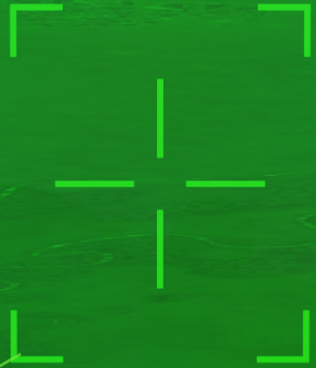
Snowplow or Stabilized Pointing Mode (when slewing and/or Target not designated)

Target Designated (Snowplow)

Area Track
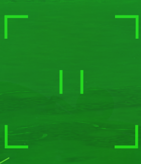
Point Track


LTD/R

- LTD/R Status - The status of the LTD/R is indicated here and on the HUD.
- LTD/R (flashing): Laser is currently firing and is able to determine range. The FLIR reticle flashes.
- LTD (flashing): Laser is currently firing and is not able to determine range. The FLIR reticle flashes.
- L ARM: Laser is armed. This is indicated when automatically armed prior to firing for weapon delivery or when the TRIG option is boxed.
- LTD (steady): Laser is not in one of the above conditions.
- TRIG: When boxed, TRIG arms manual lasing with the trigger. If TRIG is boxed, the A/G Gun is removed from the STORES format and is deselected if previously selected.
- UFC - UFC option to set the laser code and the current LTD/R code. In A/G master mode, if the LTD/R code does not match the code set for the selected weapon, the code indication flashes on the FLIR format and a flashing [CODE] legend is displayed on the HUD.
LTD/R Operation
- Manual Operation - The LTD/R can be manually fired with the TRIG option on the FLIR Format. This results in the LTD/R being fired while the trigger is held down.
- Automatic Ranging - Not yet implemented.
- Automatic Weapon Designation
- Laser-Guided Bombs - When an LGB is released, the LTD/R fires continuously beginning a preset time prior to time to impact and then until the predicted time to impact + 10 seconds. When the laser has completed firing, the LTD/R switch automatically moves to the SAFE position.
- AGM-65E Maverick - When the laser (E) Maverick missile is selected, holding the Weapon Release Button will simultaneously begin lasing the target and uncage the Maverick. Once locked onto the laser, the Maverick is automatically fired. The laser remains on until the predicted time to impact + 10 seconds and then automatically moves the switch to SAFE.
LST

- Wide / Narrow Search - This toggles whether the LST searches in a wide or narrow pattern.
- UFC - This allows for the LST laser code to be set.
- LST - This toggles LST operation. Above is the current LST laser code.
The LST is operated by pressing the LST pushbutton on the FLIR format or via the Cage/Uncage button. The LST will begin search centered on where the FLIR was last pointed. When searching, an LST legend flashes on the top of the FLIR format and on the HUD. When a laser is successfully tracked, the LST legend is solid.
When a laser is being tracked, the FLIR format will show the video feed centered on that laser and a Target can be designated with TDC depress. When the LST is in search, the video feed is blank.
A/A FLIR Format
The air-to-air FLIR format is accessed from the [TAC] menu whenever in A/A master mode. Alternatively, it can be selected from the Azimuth/Elevation format by pressing the pushbutton option or using the TDC cursor.
The following modes of operation are available:
- Snowplow - The FLIR is slewed freely and stabilized to the aircraft itself. This is the default mode when not in RRSLV, VVSLV, or Point Track.
- Velocity Vector Slaved - The FLIR is slaved to the line of sight to the velocity vector. This is commanded by boxing the VVSLV option on the A/A FLIR format when there is no L&S and not in Point Track.
- Radar Slaved - The FLIR is slaved to the extrapolated line of sight to the Radar's L&S trackfile. This is accessed by boxing the RRSLV option on the A/A FLIR format when an L&S exists and not in Point Track.
- Point Track - The FLIR itself tracks an airborne target. Point Track is accessed by "bumping" the Sensor Control Switch in the direction of the FLIR format with the TDC already assigned. This can be done from any other mode. It will attempt to acquire a recognized target within the FLIR reticle. Point Track mode is only entered when a successful track is acquired.
Non-PTRK Format
- Radar Slaved/Velocity Vector Slaved - Toggles Radar Slaved mode when an L&S exists and Velocity Vector Slaved mode otherwise.
- TDC - Assigns the TDC to the FLIR format. (The Sensor Control Switch can still be used.)
- FLIR Reticle - This is the FLIR reticle and indicates the center, and also where the FLIR will search when acquiring Point Track. The square corners indicate the FLIR is in wide FOV.
- L&S TD Box - A square target designator (TD) indicates the line of sight to the L&S trackfile whenever the FLIR is not in Radar Slaved or Point Track mode.
PTRK Format

- STT - Commands the Radar to initiate STT on the FLIR Point Track target. The FLIR remains in Point Track.
- Radar Silent - Behaves identical to the Silent option on the Attack format.
- Point Track Reticle - Two horizontal gates indicate the Point Track center upon successfully entering Point Track.
A/A FLIR HUD Indications
On the HUD/HMD, the line of sight to the FLIR Point Track target is superimposed on the HUD as follows. The avionics will correlate the FLIR target and the L&S or DT2 trackfile if determined to be the same, and as such the symbology will differ dependent on correlation and existence of an L&S/DT2 track.
- No L&S exists - A square TD box is superimposed on the HUD to indicate its line of sight and an F below indicates the source is the FLIR.
- DT2 and/or L&S exists, FLIR not correlated - When the FLIR target is not the same as the L&S/DT2, it is indicated by a small "X" (this is noticeably smaller than the DT2 "X") independent of the L&S TD box and DT2 TD X.
- FLIR correlated L&S - When the FLIR target and L&S are the same, a single TD box is displayed for the L&S as normal, with a C underneath to indicate it is correlated to the FLIR target as well.
- FLIR correlated DT2 - The DT2 is indicated by only the smaller "X" symbol when the FLIR and DT2 are correlated.